The technology can indeed neutralize human disability; with this in mind let us use the power of Arduino and simple sensors to build a Blind man’s stick that could be a lifesaver for visually impaired persons. An Ultrasonic sensor will be installed in a stick which will sense the distance of a person from any obstacle, an LDR to sense lighting conditions and an RF remote which the blind man could use to remotely locate his stick. All the directions will be given to the blind man through a Buzzer. We can use a vibrator motor in place of Buzzer and advance a lot more using our creativity.
How To Use Arduino In Designing The Circuit?
Now as we know the abstract of the project, let us move forward and gather different information to start working. We will first make a list of the components, then study them briefly, then assemble all the components to make a working system.
Step 1: Components Needed (Hardware)
Step 2: Components Used (Software)
Step 3: Studying The Components
Now as we have made a list of all the components that we are going to use in this project. Let us move a step further and go through a brief study of all the main components.
Step 4: Assembling The Circuit
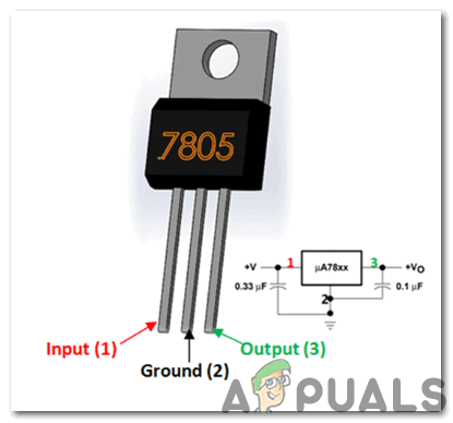
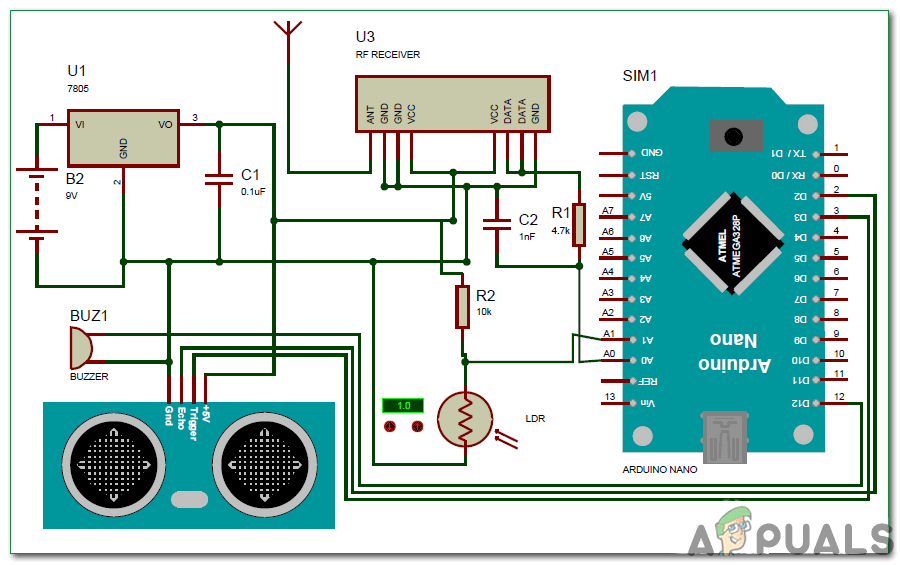
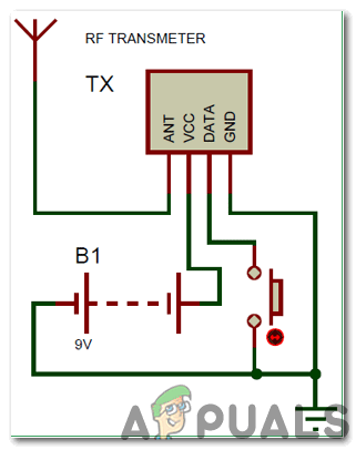
We will need to design two circuits for this project. The first circuit will be placed at a suitable place in a blind man’s stick and the second one will be an RF transmitter circuit and it will be used to find out the main circuit. Before designing the circuit on Proteus we need to include the proteus library of RF receiver in the software. You can download the library from Here and after downloading the library open the Library folder and copy MODULO_RF.LIB file and paste it in the Library folder of Proteus. In case you don’t find the library folder, click on (C:\Program Files (x86)\Labcenter Electronics\Proteus 8 Professional\LIBRARY). When you have done this open MODELS folder and copy RX.MDF and paste it in the proteus MODELS folder. In case you don’t find the models folder, click on (C:\Program Files (x86)\Labcenter Electronics\Proteus 8 Professional\MODELS). The microcontroller which will be used to control all of the sensors in the circuit is Arduino Nano. The power supply used for working of the circuit is 9V battery and this 9V voltage is dropped down to 5V using a 7805 Voltage regulator. It can be seen in the circuit that the Ultrasonic sensor is powered by the Vout of the voltage regulator. The trigger and echo pins of the sensor are connected to pin 3 and pin 2 of Arduino respectively. The Light Dependent Resistor (LDR) is connected to the potentiometer of value 10k and the Analog to Digital conversion pin A1 of Arduino is connected to that point to note the voltage difference. We need to know the signal that is emitted by RF receiver so we have connected ADC pin A0 to read the signal from RF receiver. The output of the whole circuit is given by the buzzer so, the positive pin of the buzzer is connected to the pin 12 of Arduino and the negative pin is connected to the ground of the ultrasonic sensor. We haven’t included the RF transmitter in our circuit diagram because we will assemble it on hardware separately. Whenever we use 433 MHz superheterodyne transmitter and receiver we need a microcontroller to interface them with that but in this project we need the only transmitter to send signals to the receiver so, we have connected the data pin of the transmitter with the Vcc. The data pin of the receiver is passed through the RC filter and then connected to the data pin A0 of the Arduino respectively. We will press the push button placed on the transmitter repeatedly and when the button is pressed the receiver will give any constant value as output.
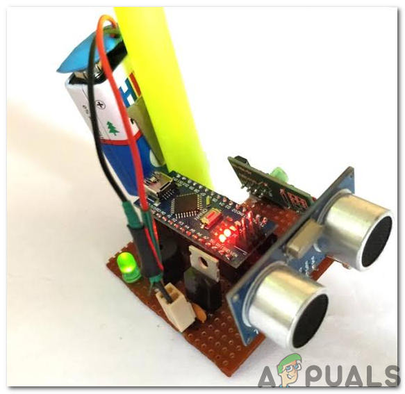
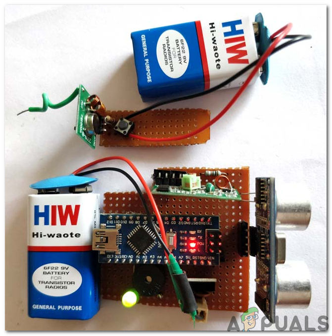
Step 5: Assembling The Hardware
As we have run the simulation no we are in a position to make a prototype. While soldering the components on the Perf board pay special attention towards the pins of Arduino Nano. make sure that the pins don’t touch each other, otherwise, Arduino could be damaged. Find a stick at your home and attach the circuit comprising of Arduino and RF receiver on it. You can use Hot glue gun for attaching the circuit on the stick and it is better to put some glue on the positive and negative terminals so, that the wires of the power supply may not be detached if the stick is stroked firmly onto the ground.
Step 6: Getting Started With Arduino
If you are not familiar with Arduino IDE before, don’t worry because below, you can see clear steps of burning code on the microcontroller board using Arduino IDE. You can download the latest version of Arduino IDE from here and follow the steps below: To download the code, click here.
Step 7: Understanding The Code
The code is well commented and self-explanatory. But still, it is explained below: 2. void setup() is a function that is used to set al the pins used, as INPUT and OUTPUT. Baud Rate is defined in this function. Baud Rate is the speed of communication by which the microcontroller board communicates with the sensors integrated with it. 3. Now, we will create a function that will calculate the distance. 4.void loop() is a function that runs repeatedly in a cycle. In this function, we tell the microcontroller board how and what operations to carry out. In the main loop, we will read the data of the sensors. Here, first, the trigger pin is set to send a signal which will be detected by the echo pin. Some conditions are applied to sound the buzzer continuously if an object is detected at a particular distance. The buzzer will beep with a small break in it if it detects dark and will beep with a slightly greater break if it detects bright.
Step 8: Testing
As we have understood the code, uploaded it on the microcontroller and assembled the hardware too, now it’s time to test our project. Before testing ensure that the connections are made correctly and verify the continuity of the circuit using the Digital Multi Meter. For turning ON both of the circuits use 9V battery. Place an object onto the surface at which you are testing and move the Ultrasonic sensor in front of it and it is noticed that the sound of the buzzer increases as the sensor moves closer to the object. There are two possibilities if the LDR is covered in dark or if you are testing in the sunlight the buzzer will start beeping. If the push button is pressed on the RF transmitter the buzzer will beep for a long time. If the buzzer keeps beeping for a long time it means that the alarm is falsely triggered. If you are facing this kind of error open the serial monitor of the Arduino IDE and check for the parameters that are causing such kind of problem. That was the simplest way to make a smart stick for blind people using Arduino. Follow all of the steps mentioned above and after successful testing of the project look for a disable person and offer him this project to make his/her life easier.
How To Make A Smart Trashcan Using Arduino?How To Make A Smoke Alarm For Your Kitchen Using Arduino?How To Make A Digital Thermometer Using Arduino?How To Make Obstacle Avoiding Robot Using Arduino?