A Simple metal detector circuit can be made at home on a small scale. In this project, we are going to make a simple metal detector circuit using a proximity sensor. All the components that are used are very simple and easily available in the market.
How To Design A Metal Detector Circuit Using TDA0161?
Now as we know what we are going to do in this project, let us start collecting further information by making a complete list of components and going through a brief study in the first place.
Step 1: Collecting The Components
The best approach to start any project is to make a list of components and going through a brief study of these components because no one will want to stick in the middle of a project just because of a missing component. A list of components that we are going to use in this project is given below:
Step 2: Studying The Components
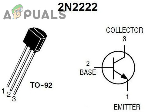
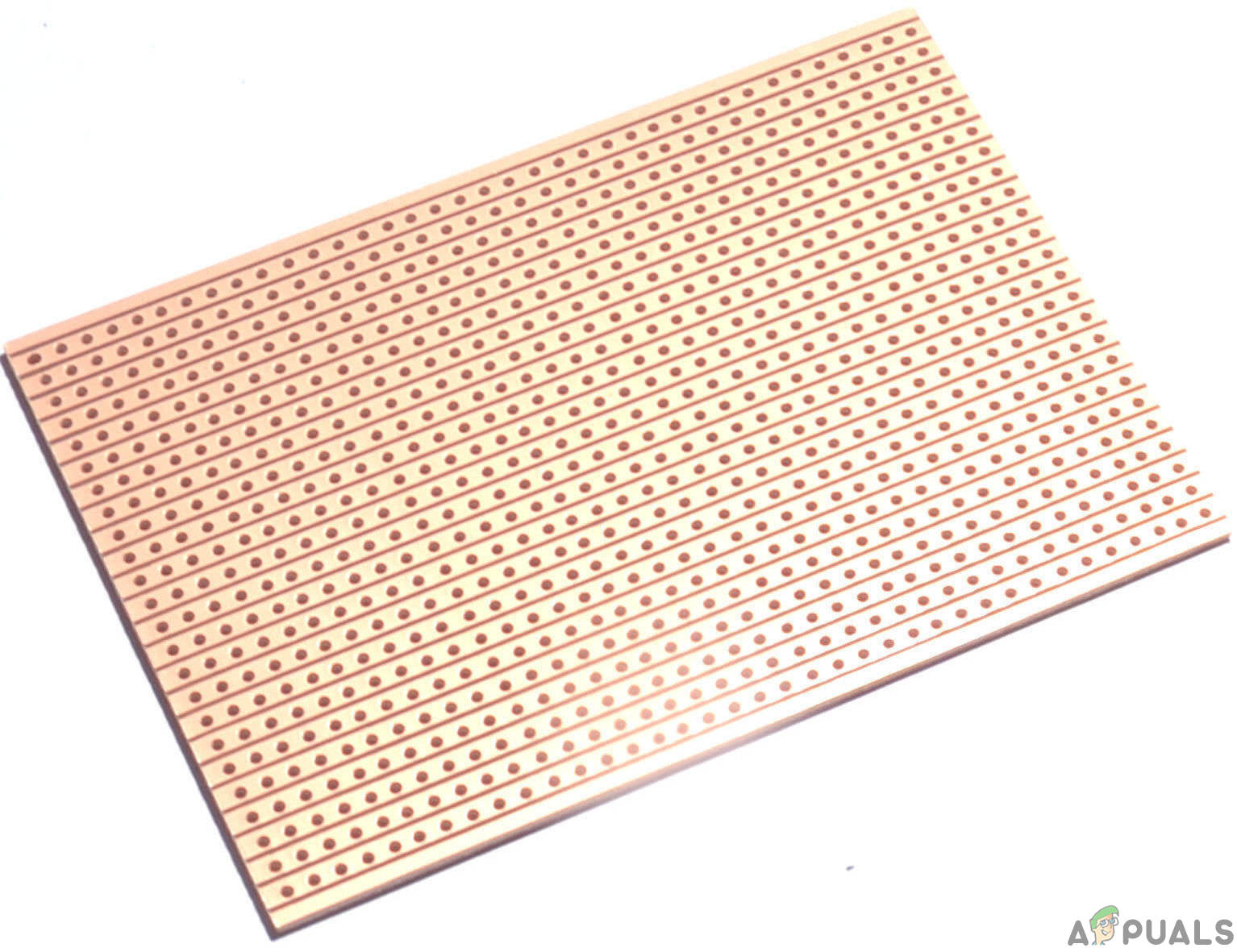
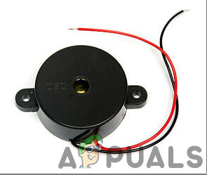
As we now know the main concept behind this project and we also have a complete list of components, les move a step ahead and go through a brief study of some main components that will be used in making f the circuit. TDA0161 Proximity Detector IC is a Proximity Detector Ic. It is manufactured by STMicroelectronics. It is used to detect metal objects. It performs this task by detecting slight changes in the high-frequency eddy currents losses. With the help of an eternally tuned circuit, the TDA0161 IC accts as an oscillator. The output signal is determined by the change in the supply current. This means that the current will be high when a metal objected will be near to the coil and the current will be low if there is no metal object near the coil. TDA0161 IC consists of 8 pins. This IC comes in dual-inline packages. 2N2222 Transistor: It is the most renown NPN bipolar junction transistor. This transistor is mostly used for switching and amplification purposes. The main reason behind its fame is that it is low cost, small size and its ability to handle a high value of current as compared to the similar small transistors. Normally this transistor can handle a high current rating up to 800mA. This transistor is made up of silicon or germanium material. In the process of amplification, the input analog signal is applied to its collector and the output amplified signal is sent to the base. this analog signal could be a voice signal. Veroboard is a good choice to make a circuit because the only headache is to place components on Vero-board and just solder them and check the continuity using the Digital Multi Meter. Once the circuit layout is known, cut the board into a reasonable size. For this purpose place the board on the cutting mat and by utilizing a sharp blade (securely) and by taking all the safety precautions, more than once score the load up top and base along the straight edge (5 or multiple times), running over the apertures. After doing so, place the components on the board closely to form a compact circuit and solder the pins according to the circuit connections. In case of any mistake, try to de-solder the connections and solder them again. Finally, check the continuity. Go through the following steps to make a good circuit on a Veroboard. The buzzer is a sort of electronic sound collector with a coordinated structure. It is generally utilized as a voice gadget in electronic items like PCs, printers, replicating machines, alert mechanical assembly, electronic toys, auto electronic gadgets, phones, etc..In this project, we are going to utilize a buzzer to sound an alarm when the pin is picked out of the main circuit.
Step 3: Block Diagram
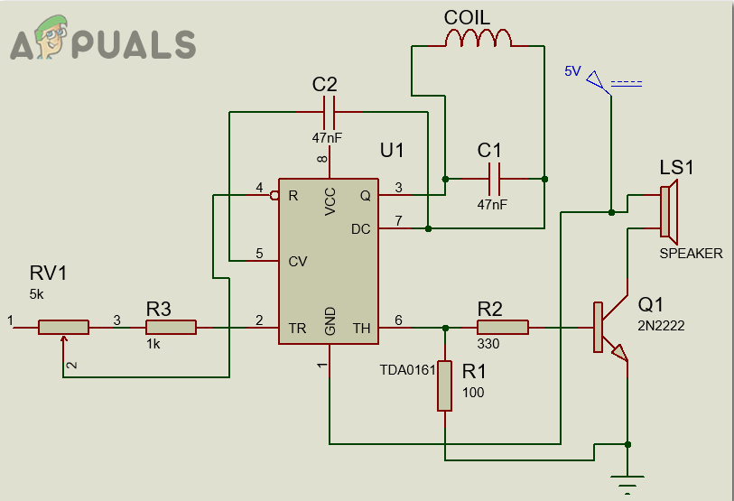
The three main arts of the metal detector circuit are LC Circuit, Proximity Sensor, output Buzzer and LED. The LC circuit is made by connecting a capacitor and a coil of copper wire in a parallel configuration. When the coil will detect the metal near its surface, it will trigger the proximity sensor which will then send the signal to the output circuit and it will turn the LED on and sound the buzzer. So basically in the LC circuit, when a material of the same frequency will come near the copper coil, it will start resonating. This will start charging the capacitor. The capacitor and inductor will be charged alternatively in the LC circuit. When the capacitor will be charged fully, the charge will be transferred to the inductor and when the charge across the capacitor nearly approaches zero, it will draw charge from the inductor. This process repeats itself again and again. A Proximity Sensor is a sensor that is used to detect n object without any physical contact. The working principle of an IR sensor and a proximity sensor are the same. It also emits a signal and it does not show anything on the output till there is any change in the reflected signal. There are so many types of proximity sensors available in the market, we are using the one which will send an output signal when it detects a metallic subject.
Step 4: Working of The Circuit
As we now have all the necessary information about the components used and the working of the circuit, let us move one step ahead and start understanding the main working of the metal detector circuit. The main Metal detector part of the circuit is the parallel configuration of the capacitor and the inductor coil. This LC circuit helps the proximity sensor to oscillate at a particular frequency. When any metallic object d any resonating frequency brought near to the inductor coil, due to the law of electromagnetic induction, an induced current will be induced in the coil by mutual induction. This will alter the signal flowing through the coil to the proximity sensor. A potentiometer is a variable resistor whose value can be changed. It is used in this circuit to change the value of the LC circuit. It must be kept in mind that the value of the proximity sensor should be checked when no metallic object is near the coil. If the coil has a metallic object near it, the value of the proximity sensor will be changed because the LC circuit will have a different signal in it. Now the changed signal in the coil is sent to the proximity sensor. this sensor will examine this signal and react accordingly. If the signal is of around 1mA, it means that there is no metallic object near the coil. If the current is almost more than 8mA, it indicates that there is a metallic object near to the coil. So, when the output pin of the proximity sensor is high, a positive voltage will be provided to the transistor and it will send a signal to switch on the LED and the buzzer.
Step 5: Assembling The Components
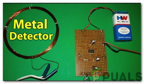
Now as we know the main working and also the complete circuit of our project, let us move ahead and start making the hardware of our project. One thing must be kept n mind that the circuit must be compact and the components must be placed so close. The circuit will look like the image below:
Advantages
As every project has its pros and cons, some of the advantages and disadvantages of this metal detector circuit are listed below.
Disadvantages
As this is a small scale homemade metal detector circuit, the main disadvantage of his circuit is the issue with its range of detection. For this circuit, the distance of a metal object should be at least 10mm from the metal detector circuit’s coil.
Applications
There are several applications of a metal detector. Some of these are listed below.
How To Make A Cell Phone Detector Circuit?How To Make An Intercom Circuit To Exchange Voice Signal Between Two Points?How To Make a Pickpocket Alarm Circuit?How To Make Automated Washroom Light Switch Circuit?